Cardboard Recycling Plant Layout and Space Requirements
A cardboard recycling line can fit inside a building on a supplier’s first drawing and still be almost impossible to operate. The machines start. Then the real problems appear: a trailer blocks the only door, incoming bales occupy the forklift lane, a gearbox cannot be withdrawn, finished bales turn in front of the control cabinet, and dust ducting competes with the sprinkler mains.
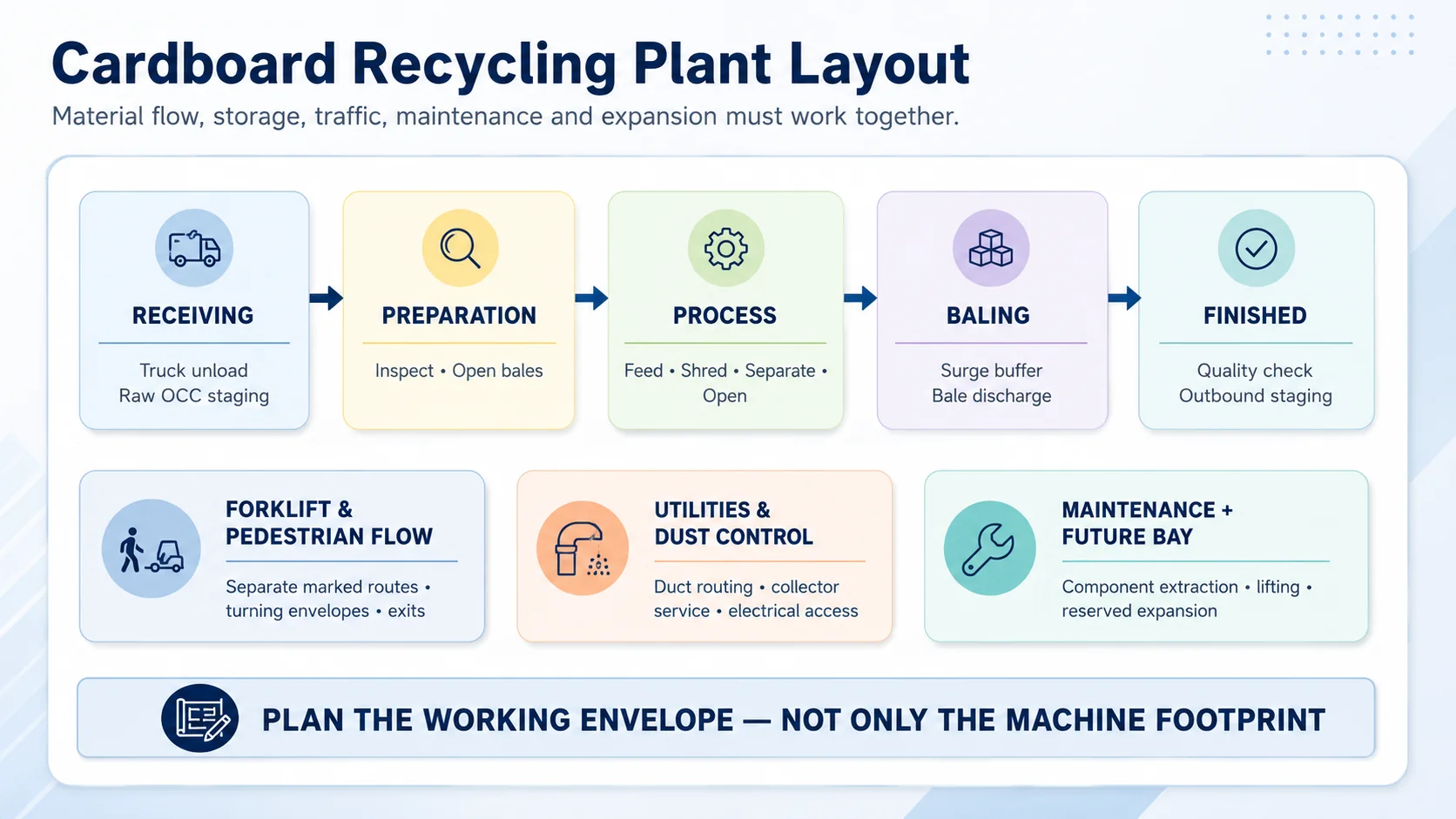
A workable OCC layout connects receiving, preparation, processing, dust control, baling and storage without forcing trucks, forklifts, operators and maintenance work into the same space.
The Space Number You Need Is Not the Equipment Footprint
There is no defensible universal “square meters per tonne per hour” rule. Two lines with similar throughput can need very different buildings when one receives flattened loose OCC every day and the other stores wired bales for a week. The practical method is to size each zone, draw the traffic paths, test maintenance access and then add the areas that are usually forgotten.
Divide the Facility Into Eight Working Zones
One equipment list rarely produces a good layout by itself. We normally sketch the cardboard recycling plant as zones first and place exact machines later. This prevents the main line from consuming every convenient square meter before storage, traffic and maintenance are considered.
Zone
What must fit
Common hidden requirement
1. Receiving and raw staging
Truck or van unloading, loose OCC or bale storage, inspection and quarantine
Door approach, trailer tail swing, rain protection, damaged or wet material isolation
2. Feed preparation
Bale wire or strap removal, sorting, bale opening, loose-box flattening or metering
Feed conveyor, shredder, magnet, transfer conveyors, fiber opening and optional separation
Guarding, platforms, access stairs, emergency-stop reach, spill and clean-up space
4. Maintenance envelope
Service aisles, component removal paths, lifting and temporary parts placement
Rotor, shaft, gearbox, screen, belt or motor extraction without dismantling another machine
5. Utilities and dust control
Electrical room or cabinets, air system, dust collector, ductwork, compressor and fire controls
Explosion/fire review, safe discharge direction, filter service and waste-dust removal route
6. Output and finished storage
Surge buffer, baler, bale discharge, weighing, labeling and outbound staging
Forklift turning, tying cycle, rejected bale area and enough stock for shipping rhythm
7. Rejects and housekeeping
Metal, wire, plastic film, dust, wet board and general waste containers
Containers accessible without crossing the product route; clean-up equipment storage
8. People, traffic and expansion
Pedestrian routes, exits, control position, welfare space, forklift lanes and spare bay
Future conveyor extension, second shift support, additional separator or larger baler
The complete cardboard recycling plant equipment list identifies which modules may be present. This article intentionally does not repeat each machine’s function. The layout task is to give those modules enough room to work together safely and to be maintained.
Use a Zone-Based Space Calculation
A useful first-pass equation is:
Gross indoor process area = equipment envelope + operating and maintenance access + raw-material staging + finished-product staging + utilities and rejects + circulation and egress + reserved expansion.
This is not a building-code calculation. It is an engineering worksheet that forces every function to appear on the plan. External truck queuing, trailer parking, fire lanes, weighbridge approach, outdoor bale storage and stormwater controls must be calculated separately as site area.
Do not apply one arbitrary allowance to the machine footprint. Calculate the operating zones separately, then test the combined drawing against real handling and maintenance tasks.
Step 1: lock the required production basis
The line rate affects conveyor width, buffer volume, bale frequency, dust pickup and daily storage. Use sustained complete-line throughput rather than the peak rating of one machine. The waste cardboard recycling plant capacity guide separates nominal rate, continuous throughput, shift input and accepted output. For layout, the daily gross feed and daily finished output are often more useful than one t/h number because storage and truck movements happen by shift and by day.
Step 2: obtain the supplier’s general-arrangement envelopes
Ask for the plan view and elevation of every machine, conveyor, platform, hopper, duct and cabinet. The drawing should distinguish the steel footprint from doors, guarding, stairs, access panels and component-removal paths. Sometimes a machine is only two meters wide but needs a much wider temporary service zone when a shaft or rotor is withdrawn.
Step 3: calculate inventory by operating policy
How many days of OCC will be kept on site? Is the storage target based on gross wet feed, accepted grade or contractual minimum stock? How many finished bales accumulate before collection? Storage policy, not throughput alone, often dominates the building area.
Step 4: draw movement paths at real scale
Show the largest inbound vehicle, loader, forklift and finished bale. Add turning envelopes and door positions. Then trace people walking to the control station, inspection points, exits and maintenance areas. EPA material-recovery-facility guidance emphasizes efficient and safe movement and storage, adequate truck access and turning, space for queuing, and minimizing cross traffic.[1]
Step 5: test abnormal but foreseeable operations
A normal production animation is not enough. Place a stopped forklift beside a finished bale. Open the largest maintenance door. Put a waste container at the reject discharge. Simulate a wet or rejected incoming load. Show how a fire department vehicle reaches the building. A layout should survive these conditions without losing every aisle.
Machine Footprint, Operating Clearance and Maintenance Clearance Are Three Different Things
Catalog dimensions are a starting point. They usually do not answer the questions a contractor and maintenance team will ask during installation.
Operating clearance
Operators need room to inspect material, see the feed, reach controls, remove small spills and observe discharge points without entering a vehicle path. Conveyor pull cords, emergency-stop devices and manual reset points need unobstructed access. Guards and interlocked doors must be able to open as designed.
Maintenance clearance
For each major component, write the maintenance action beside the drawing. “Change belt,” “withdraw shaft,” “remove screen,” “lift motor,” “open shredder chamber,” “replace filter element.” Then draw the tool, lifting device and temporary laydown area. The selected double-shaft shredder, for example, should be reviewed as an installed service task, not just a rectangular footprint.
In practice, the extraction direction matters as much as the clearance distance. A gearbox can have generous space on one side and still be trapped by a structural column, conveyor leg or wall. We normally recommend identifying a permanent “do not build” maintenance corridor on the general-arrangement drawing.
Construction and installation clearance
The final building also has to receive the equipment. Check door width and height, internal crane or forklift capacity, roof openings, floor pits, anchor access and the sequence in which modules are installed. Retrofitting a line around existing columns can save building cost, but only when the equipment can still be delivered and assembled.
Electrical access is not spare storage
Control cabinets and disconnects often end up beside a wall because the space looks convenient. Their required working clearances depend on the installed electrical system and applicable code. Mark the electrical working area on the floor plan and keep it out of bale, pallet and waste-bin storage.
Calculate Raw OCC and Finished-Bale Storage From Inventory
Storage is where many early layouts become unrealistic. A designer draws one or two bales beside the conveyor. The operator needs two days of feed, a quarantine pile and enough finished stock to fill an outbound load.
Baled OCC storage worksheet
Use these calculations before choosing the storage block:
Required raw storage mass = daily gross feed × planned storage days.
Number of bale positions = required storage mass ÷ average actual bale mass.
Base bale floor area = bale positions × actual bale plan area ÷ approved stack layers.
That base area still excludes aisles, wall separation, sprinkler clearance, damaged-bale handling, column losses and fire compartmentation. Bale mass and dimensions should come from the user’s own deliveries. “Standard OCC bale” is not precise enough for a final layout.
Stacking height must be decided with the site’s structural, fire and operating requirements. OSHA identifies crushing hazards from unstable paper storage, while insurer and fire-code guidance may set pile dimensions, separations and sprinkler conditions.[4] Do not use maximum forklift lift height as the storage-height rule.
Then divide by the practical fill height and apply a realistic usable-volume factor for the bunker or floor bay. This factor accounts for sloped piles, irregular boxes, access and the fact that the entire geometric volume cannot normally be filled. Measure bulk density from representative material and handling conditions. Flattened cartons, unflattened boxes and mixed paper can differ dramatically.
Finished bales create their own rhythm
Finished-product space depends on bale cycle, collection schedule and quality control. Include the active discharge position, forklift pickup position, finished stock, rejected or retied bales and loading staging. The baler discharge area should not double as the only route to an emergency exit or control cabinet.
Design Truck, Forklift and Pedestrian Flow Before Finalizing the Line
MRF design guidance treats external access and internal traffic as core design tasks, not details to be resolved after equipment selection. EPA guidance recommends enough site room for large tractor-trailers to park and turn, suitable scale queuing where used, and layouts that reduce intersections and cross traffic.[1]
Prefer one-way material flow
The cleanest arrangement receives OCC at one end and dispatches finished bales at the other. It reduces backtracking and makes expansion easier. That isn’t always possible in an existing building, but the principle remains useful: inbound material, reject containers and finished product should cross as little as possible.
Separate public or employee cars from industrial traffic
Inside the factory, provide clearly defined pedestrian routes to the control station, welfare areas and emergency exits. Where visibility is poor or heavy vehicles reverse frequently, painted floor markings may not be enough. A site-specific risk assessment may require physical barriers, controlled crossing points, mirrors, warning systems or restricted-access zones.
Door dimensions are only half the question
A trailer may fit through a door but still lack approach distance. A forklift may clear the opening and then be unable to turn with a bale. Check door width, clear height, apron depth, dock level, drainage, weather exposure and the position of columns or bollards immediately inside.
Keep normal storage out of circulation space
One export project looked acceptable until the operating team placed the first two days of raw bales on the floor. The marked forklift route disappeared. The fix was not a wider aisle; it was a separate storage block with a controlled feed-staging lane. Layout drawings should show maximum normal inventory, not an empty warehouse.
Clear Height Is a Process Dimension
Buyers often provide workshop length and width but estimate clear height from the tallest machine. A dry cardboard line has several vertical layers: hopper loading, inclined conveyors, elevated transfer points, access platforms, dust hoods and overhead ducts. Structural beams, lights, cable trays and sprinkler pipes reduce usable height further.
Check the highest of these conditions:
the machine or conveyor in its normal operating position;
the loader bucket or bale-opening motion at full travel;
platform guardrails, stairs and required headroom;
dust ducts, dampers and filter service access;
sprinkler clearance and the approved storage height below it;
the lifting path for motors, shafts or other heavy components;
future conveyor elevation if another module is added.
A tall building does not automatically solve the problem. A low beam across one transfer point can force the entire conveyor profile downward. Ask the supplier for a vertical section through the critical line, and provide the actual underside elevation of beams rather than only the nominal eave height.
Fire Protection, Paper Dust and Egress Change the Layout
Cardboard is combustible, paper dust may be explosible under some conditions, and recycling operations combine stored fuel with conveyors, bearings, electrical equipment and mobile vehicles. These issues require project-specific engineering and approval by the authority having jurisdiction. They should also be discussed before the building is filled with equipment.
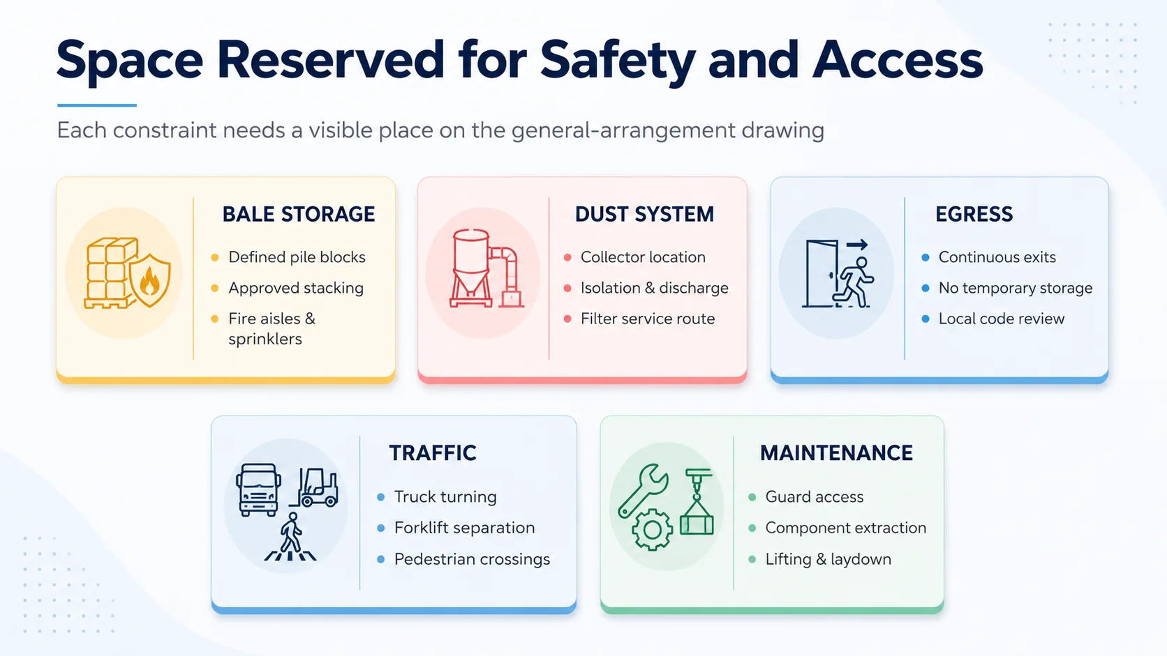
Bale storage needs defined piles and aisles
AIG’s paper-recycler fire-prevention bulletin is insurer guidance rather than a building code, but it illustrates why a large empty rectangle cannot be treated as unrestricted bale storage. Its recommendations include defined pile sizes and aisles, separation from walls and equipment, sprinkler considerations, and greater separation for outdoor storage.[5] Applicable fire code, insurer requirements, commodity condition, building construction and sprinkler design must control the final arrangement.
Dust collection is part of the building layout
OSHA lists combustible dust among paper-recycling hazards, and its technical guidance describes ignition and deflagration risks associated with fine combustible material, transfer points and dust-collection systems.[2][3] The final design may need explosion protection, isolation, safe vent or discharge direction, grounding and bonding, suitable housekeeping methods and restrictions on returning air indoors. A qualified combustible-dust assessment should determine the actual measures.
This is why the dust collector should not be dropped into the only leftover corner. Its location affects duct length, pressure loss, structural support, access for filter changes, dust-bin removal, fire-department approach and the direction in which a protected event could discharge.
Emergency egress is not an adjustable production buffer
For U.S. general industry, OSHA requires exit access to be at least 28 inches (71.1 cm) wide and exit routes to remain free and unobstructed.[6][7] That is a regulatory minimum for exit access, not a recommended operating aisle width for forklifts or maintenance. Occupancy, local building and fire codes, travel distance, door capacity and site hazards may require substantially more.
Fire storage, dust control, exits and traffic cannot be added as notes after the line is fixed. Each one consumes real space and changes the feasible arrangement.
Three Practical Cardboard Recycling Layout Patterns
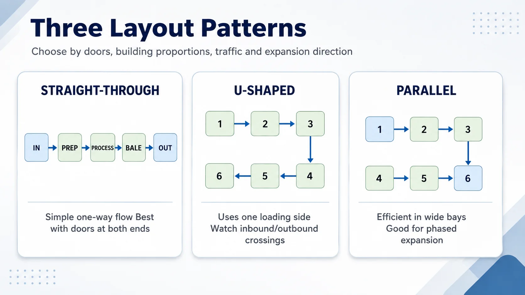
Straight-through, U-shaped and parallel layouts can all work. The best choice depends on door positions, storage policy, building columns, traffic and the preferred expansion direction.
1. Straight-through layout
Material enters at one end, moves through preparation and processing, and leaves as finished bales at the opposite end. This is usually the easiest flow to understand. It supports one-way material movement and gives each end of the building a clear logistics role.
Best fit: a long rectangular building with separate inbound and outbound access.
Watch for: a long dust duct, a distant operator position, and expansion that can only occur at one end unless a side bay is reserved.
2. U-shaped layout
The line turns so inbound and outbound logistics use the same side of the building, while the process occupies the center and far wall. This can suit a facility with doors on only one elevation.
Best fit: an existing warehouse with a shared loading yard and enough internal width for the turn.
Watch for: crossing forklift routes, raw and finished inventory becoming mixed, and tight transfer points at the bend.
3. Parallel or split-zone layout
Receiving and preparation run along one bay, while downstream processing and baling run in a parallel bay. Transfers cross between them at selected points. This pattern can use a wide building efficiently and may isolate dusty or noisy stages.
Best fit: a wide multi-bay building or a phased project that will add modules later.
Watch for: structural columns at transfer points, duplicated pedestrian crossings and longer internal forklift travel.
We normally compare at least two arrangements before freezing the quotation. A waste cardboard recycling machine selection should include layout review because the “best” module configuration can change when the building has low beams, limited doors or no safe expansion direction.
A Worked 1,000 m² Indoor Layout Example
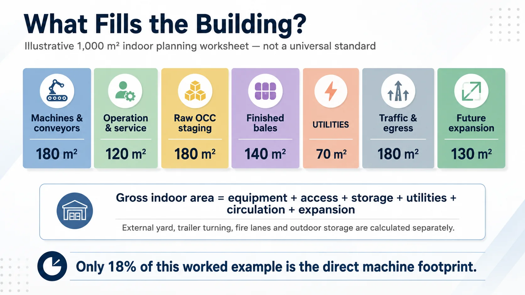
The following example demonstrates the worksheet. It is not a YUXI standard footprint, a code-compliant design or a capacity guarantee. Assume a hypothetical 40 m × 25 m building with 1,000 m² of clear indoor floor area, a suitable clear height confirmed separately, and external truck maneuvering outside the building.
Planning zone
Illustrative area
Reason for the allowance
Machine, conveyors and platforms
180 m²
General-arrangement footprint of the selected dry line
Operating and maintenance access
120 m²
Permanent service corridors, guarding access and component extraction
Raw OCC staging and preparation
180 m²
Normal feed inventory, inspection, wire removal and opened-bale buffer
Finished bales and discharge
140 m²
Baler discharge, forklift pickup, quality check and outbound staging
Dust, electrical, rejects and housekeeping
70 m²
Utility access and separate waste-stream containers
Traffic, pedestrian routes and egress
180 m²
Marked circulation that remains clear at normal inventory
Future module or expansion bay
130 m²
Reserved area with a feasible conveyor and utility connection
Total
1,000 m²
Indoor planning total; external yard not included
The value of the example is not the number. It is the discipline. Only 18% of the floor is the direct machine and conveyor footprint. If a buyer had reserved 250 m² based on a footprint drawing plus a small margin, the building would fail before normal storage and traffic were added.
Now test the example. If raw OCC inventory must increase from one day to three, which zone expands? If the finished-bale truck collects twice a week instead of daily, can the stock remain within the approved pile arrangement? If a light-reject separator is added, does the reserved bay have the correct elevation and dust connection? These questions turn a static drawing into an operating plan.
How to Audit an Existing Building
Existing warehouses can work well, but their advertised floor area is less useful than a dimensioned obstruction plan. Measure and photograph the following:
Building item
What to record
Why it matters
Columns and walls
Grid spacing, column size, braces and fire walls
Controls conveyor alignment, service corridors and pile blocks
Vertical obstructions
Beam undersides, trusses, lights, sprinklers, pipes and cable trays
Determines actual clear height at every transfer point
Doors and yard
Clear opening, apron, dock, approach angle and turning room
Confirms trailer and forklift access rather than doorway fit alone
Floor
Level changes, pits, cracks, drainage and verified load capacity
Affects anchors, storage stacks, mobile equipment and installation
Power and utilities
Voltage, capacity, transformer, compressed air and connection points
Can dictate electrical-room location and cable route
Fire systems
Sprinkler type, risers, hydrants, alarm, fire lanes and compartments
May limit storage height, pile arrangement and collector position
Neighbors and environment
Noise-sensitive boundaries, wind, dust discharge and truck hours
Changes building orientation and operating permissions
On one retrofit review, the nominal building height was adequate, but a diagonal roof brace crossed exactly where the feed conveyor needed to rise. Moving one machine solved the height conflict and created a forklift conflict. The final fix was a shorter transfer with a different line turn. This is typical: layout decisions are connected.
What to Send for a Preliminary Layout and Quotation
A good RFQ allows the equipment supplier to draw around real site constraints rather than a clean rectangle. Include:
a dimensioned PDF, CAD file or clear sketch showing the full site and building;
column grid, walls, doors, docks, pits, floor levels and clear height under each beam;
photos and video of the actual cardboard, including difficult loads;
loose or baled proportions, bale dimensions, average mass, wire or strap type and moisture;
required sustained complete-line capacity and working hours;
raw-material and finished-product storage days;
required output, baler arrangement and outbound collection method;
power supply, utility locations and known fire or environmental constraints;
the preferred future expansion direction and any equipment already on site.
Ask the supplier to return a plan view, critical elevations, module list, material-flow arrows, maintenance envelopes, dust-duct concept, utility loads and an exclusions list. The quotation should state whether platforms, guards, cable trays, ducts, foundations, installation, fire systems and local approvals are included. The cardboard recycling machine price guide explains why unclear site scope can create large differences between apparently similar quotations.
Layout Mistakes That Usually Cost More After Installation
Adding a percentage to the machine footprint
A blanket 20% or 30% allowance feels simple, but it does not know the storage days, bale dimensions, forklift route or component extraction path. Zone calculations are slower at the beginning and far cheaper later.
Drawing an empty warehouse
Show maximum normal raw and finished inventory. Otherwise storage quietly migrates into aisles, maintenance space and electrical access after commissioning.
Putting the main shredder in the center first
The largest machine often becomes the visual anchor. Sometimes the better starting point is the receiving door, the baler discharge or the dust collector because those items are harder to move around structural and site constraints.
Using the same route for raw bales and finished product
This creates congestion and quality confusion. Even in a U-shaped layout, establish separate staging zones and a controlled crossing plan.
Ignoring service extraction
A narrow aisle may be enough for daily inspection and useless for a gearbox replacement. Put the maintenance task on the drawing before foundations are poured.
Treating clear height as one building number
The lowest obstruction at a transfer point controls the line. Record beam and service elevations throughout the building.
Leaving dust and fire engineering until permitting
Collector location, storage blocks, sprinkler design and emergency access can force major changes. Coordinate them while alternative layouts are still inexpensive.
Using expansion space as temporary storage
Temporary storage has a habit of becoming permanent. Mark the future bay, keep its access and utilities feasible, and include it in operating procedures.
Get a Cardboard Plant Layout Review
Send your dimensioned workshop plan, column and clear-height data, material photos, loose or baled feed details, storage days, sustained capacity target and output handling method. YUXI can prepare a preliminary module arrangement and identify the site information still needed before final engineering.
Cardboard Recycling Plant Layout FAQ
How much space does a cardboard recycling plant need?
There is no reliable universal area per tonne. Required space depends on the process route, loose or baled feed, storage days, equipment service envelopes, forklift and truck circulation, fire-protection strategy, finished-bale handling, utilities and future expansion. Calculate each zone separately and then test the complete material flow.
Is the machine footprint enough for layout planning?
What clear height should an OCC recycling building have?
Clear height must be checked against the highest operating and maintenance condition, not only the tallest machine. Include loader discharge, inclined conveyors, platforms, ductwork, dust collectors, sprinkler clearance, lighting, structural members and any lifting equipment. The equipment supplier should issue a vertical general-arrangement drawing for the proposed line.
Should loose cardboard and OCC bales use the same receiving layout?
Usually not. Loose cardboard needs volume, controlled unloading and protection against bridging or windblown material. Baled OCC needs trailer access, safe unloading, bale inspection, wire or strap removal, bale opening and buffer space before metered feeding.
How should raw-material storage be calculated?
Start with daily gross feed and the required storage days. For bales, divide storage mass by average bale mass, then apply the actual bale dimensions, approved stacking arrangement and required aisles. For loose cardboard, divide mass by measured loose bulk density and include the usable fill factor of the storage bay or bunker.
Can forklift aisles be used as emergency exit routes?
Do not assume that a production traffic aisle automatically satisfies an exit-route design. Exit access must remain continuous and unobstructed, and local building, fire and occupational-safety requirements may require more width, separation or protection than a forklift route provides.
Where should the dust collector be located?
Its location should be decided through a site-specific combustible-dust and fire review. Paper dust can present fire and deflagration hazards. Collector construction, explosion protection, isolation, discharge direction, return-air arrangements, duct routing and access for inspection must be coordinated with qualified specialists and the authority having jurisdiction.
What information should be sent for a preliminary YUXI layout?
Send a dimensioned site or workshop plan, column grid, clear height, doors, truck approach, floor levels and load limits, material photos, loose or baled condition, bale dimensions and mass, target sustained throughput, storage days, power supply, output form, existing fire systems and the preferred expansion direction.
U.S. Occupational Safety and Health Administration, Paper recycling hazard guidance, including crushing risks associated with material handling and storage.
David focuses on industrial shredding and recycling equipment,including material evaluation,shredder selection,process configuration,and recycling line planning.
Speak To Our Shredder Machine Expert
Get in touch with our nice team today to get a price estimate for a shredder machine.