How Does a Hydraulic Shredder Work? Drive & Cutting Cycle
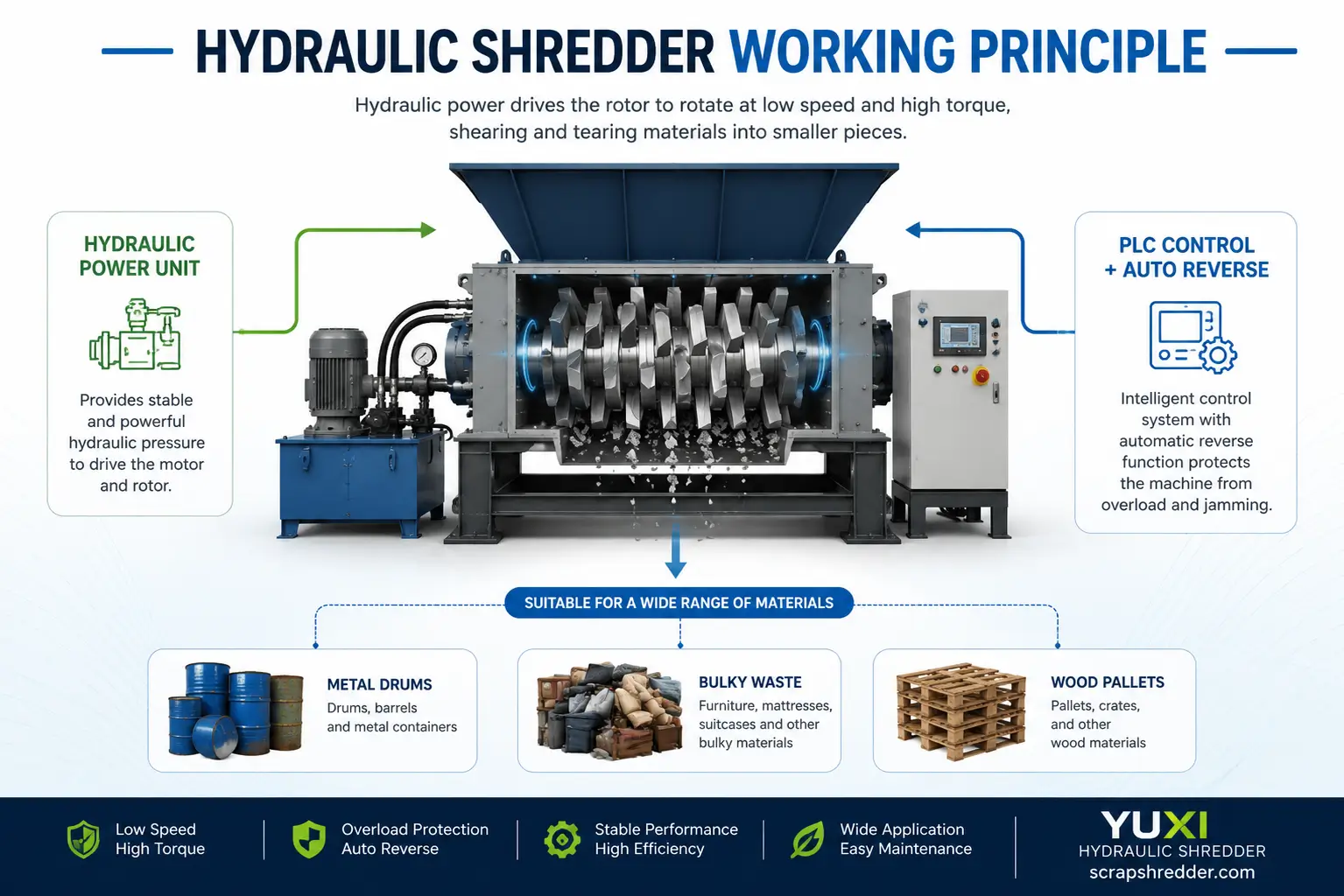
A sales video can make a hydraulic shredder look simpler than it really is. A difficult piece enters the chamber, the machine slows, the load rises, the shafts reverse for a moment, and cutting resumes. It is tempting to call all of that “the hydraulic cutting principle.” That description is too broad. On one machine, hydraulics may only move the feed pusher. On another, hydraulic motors are actually turning the cutter shafts. Once that difference is clear, the rest of the working cycle—feeding, cutting, reversing and discharge—makes much more sense.The current YUXI hydraulic shredder machine page shows both arrangements: a single-shaft version using a hydraulic pusher with screen-controlled cutting, and a hydraulic double-shaft version in which hydraulic motors drive two counter-rotating cutter shafts. Rather than repeat the product page’s broader material, price and selection information, this article follows what is happening inside the machine during one real cutting cycle.“Hydraulic shredder” can describe different architectures.
What Actually Happens Inside a Hydraulic Shredder?
Strip the machine down to its basic actions and the sequence is fairly straightforward. Electrical power runs the hydraulic or rotor drive, material is brought into the cutting zone, the cutters take a bite, the controls watch the load, and the machine changes its next movement when resistance becomes too high. So the cycle is not simply motor on → material cut. The feed and cutter are constantly reacting to one another.
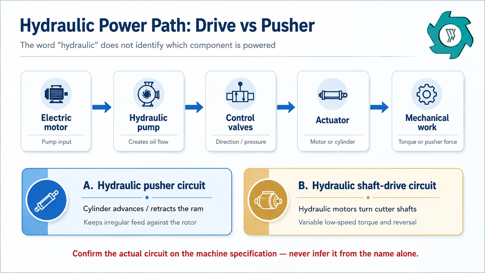
The short engineering sequence: power unit builds oil flow → valves control direction and pressure → a cylinder or hydraulic motor creates motion → material reaches the cutters → resistance changes the load → controls adjust pusher or shaft movement → correctly sized material discharges.
Where the hydraulic actuator sits is the detail that changes the whole picture. In many single-shaft shredders, it is the pusher cylinder. The pusher keeps awkward material against a rotor, the rotor knives pass fixed counter knives, and a screen holds back pieces that are still too large. In a hydraulic double-shaft machine, the actuator can instead be a hydraulic motor on each cutter shaft. The shafts grip and tear the feed directly, so the machine does not depend on a pusher for every bite.
Hydraulic Drive Is a Power-Transmission System, Not a Cutting Method
Hydraulics transmit power through pressurized fluid. Usually, the motor drives the pump. The pump supplies oil flow, while the valve directs that flow and limits system pressure. A cylinder or hydraulic motor then turns the hydraulic power into movement.Inside a shredder, that final actuator may have a completely different job from one design to another. A cylinder gives the pusher straight-line movement. A hydraulic motor gives a cutter shaft rotary movement. Both machines can be sold as hydraulic shredders, but the presence of a reservoir and hydraulic power pack does not tell you which part of the shredder is actually hydraulic.The same hydraulic power unit concept can serve a linear pusher or a rotary cutter drive. The machine specification should state which circuit is actually used.For a hydraulic shaft drive, pressure and flow are useful because they help explain what the machine is doing under load. Flow has a strong influence on actuator speed. Pressure rises as the material resists movement, allowing the system to develop force or torque until the configured limits are reached. Directional, pressure-relief and flow-control valves then determine how that energy is managed. Rexroth lists these as standard hydraulic valve functions.[1]
One quotation detail worth checking: a data sheet may show pump power, hydraulic pressure and motor size and still tell you very little about cutter behavior. For a cutting application, the useful questions are the actual drive layout, normal shaft speed, available torque or torque curve, control logic, relief settings and the material conditions used for the capacity test.
How the Hydraulic Pusher Feeds a Single-Shaft Shredder
Bulky waste does not arrive at a rotor in a neat, repeatable stream. Hollow plastic parts can bounce. Film and textiles can bridge. Wood offcuts may lie across one another. A dense lump can sit low in the hopper while lighter pieces stay above the cutting circle. The pusher deals with that inconsistency by bringing the feed to the rotor instead of leaving the whole job to gravity.The pusher should not simply press as hard as possible. Push too quickly and the rotor can be buried faster than the knives can take clean bites. Load rises, reversals become more frequent and heat starts to build. Go too far the other way and the rotor spends time running half empty. The machine may sound comfortable, but useful throughput falls.A load-responsive pusher is meant to work between those two extremes. During an easy cut the ram can keep moving forward. As resistance rises it may slow, stop or pull back slightly. Once the rotor clears the difficult section, feeding starts again. The exact pressure, current or timing thresholds depend on the machine; what matters here is that feed rate follows what the cutter can actually accept.The industrial single-shaft shredder buying guide goes further into how this architecture is specified. For the working principle, the useful takeaway is simpler: stable output comes from the pusher, rotor bite, knife condition and screen all staying in balance. Changing one of them usually changes the others.
The Single-Shaft Hydraulic Shredder Cutting Cycle, Step by Step
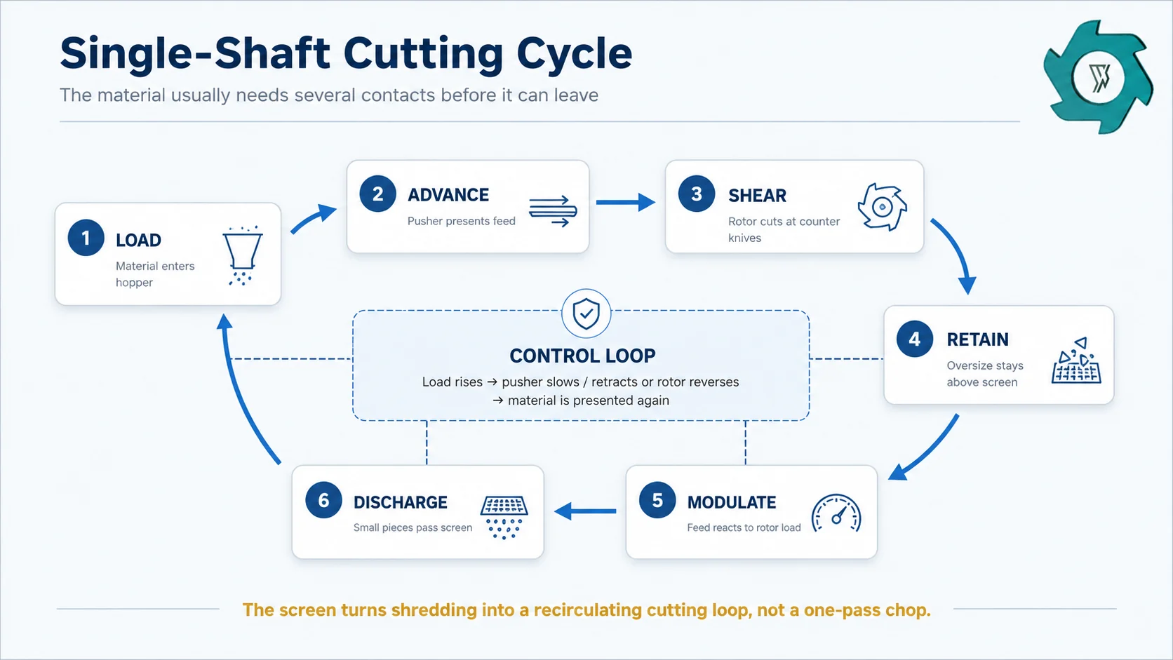
A single-shaft shredder is easier to understand if you stop picturing one object going through one clean cut. Much of the feed is presented to the rotor, cut, shifted, presented again and cut again. It may repeat that sequence several times before the material finally fits through the screen.The pusher, rotor and screen form a recirculating process. Oversize pieces stay in the chamber until their geometry allows them to pass the selected screen.
Material enters the hopper. Geometry starts to matter immediately. A long, hollow or springy part can occupy a lot of hopper volume while adding surprisingly little mass at the rotor.
The pusher moves in. Hydraulic force brings the loose material toward the cutting circle and keeps low-density feed from simply moving away from the rotor.
Rotor knives pass the counter knives. Material is carried through a narrow cutting region. The action is primarily low-speed shearing and tearing rather than high-speed impact.
Oversize pieces stay in the chamber. If a fragment cannot pass the screen, it remains near the rotor and comes back for another cutting contact.
The pusher responds to the load. A dense or awkward piece may cause the feed control to pause, retract or re-advance instead of continuing to add material at the same rate.
Small-enough material leaves through the screen. Once the fragment geometry fits the opening, it drops or is carried into the connected discharge system.
One object may go around this loop several times. A thick plastic lump might lose an edge, rotate and meet the knife again. A board can change orientation after the first bite. Flexible material may wrap briefly, release and return to the cutting zone. That is why a different screen or pusher setting changes more than just particle size; it also changes the sound, load pattern and time the material spends inside the chamber.
How the Cycle Changes on a Hydraulic Double-Shaft Shredder
A hydraulic double-shaft shredder works to a different rhythm. There is usually no single-rotor pusher-and-screen loop. Two counter-rotating shafts carry staggered or intermeshing cutter discs. As the teeth move inward, they catch the feed, draw it into the chamber and reduce it through shearing, tearing and compression.On the YUXI hydraulic double-shaft arrangement, the published drive path starts with an electric motor and hydraulic pump, then passes through the valve system to hydraulic motors and planetary reduction units before reaching the two cutter shafts. In other words, the hydraulics are doing a different job from the single-shaft pusher circuit. The key behavior here is low-speed shaft torque and the way that torque responds when the cutters meet resistance.This kind of hydraulic drive is useful on difficult feed because the shaft speed can be controlled and the direction can be changed under heavy load.The discharge should also be judged differently. A conventional twin-shaft primary shredder is normally chosen to open and reduce bulky material, not to hold every fragment in the chamber until it reaches a tight screened size. Cutter width, tooth profile, shaft spacing, material stiffness and the number of repeated grips all affect the rough output. If the downstream process needs a narrow final size, a screen or second reduction stage often makes more sense than asking the primary shredder to do both jobs.The cutter mechanics themselves are covered in How Does a Double Shaft Shredder Work?. Here the hydraulic part is the extra piece of the puzzle: controlled low-speed rotation, reversible motion and torque delivery that can react to a difficult bite.
What Happens When the Shredder Hits an Overload?
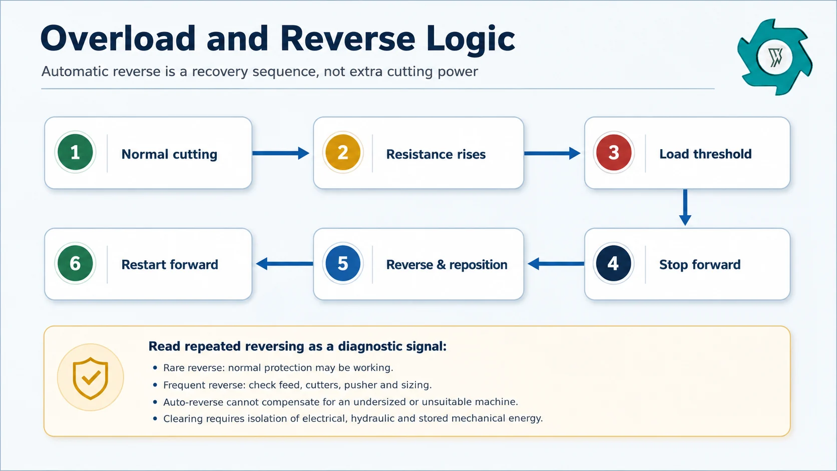
Sooner or later, every industrial shredder sees a load that is harder than the average batch. It might be a nested bundle, a dense lump, a part entering sideways, too much material dropped at once or an unexpected hard inclusion. A useful shredder is not one that somehow avoids every overload. What matters is how calmly it recovers when the load arrives.Automatic reverse protects the machine and repositions the feed. Repeated reversing is useful diagnostic information, not proof that the machine is handling the material well.With a hydraulic shaft drive, resistance in the cutting chamber shows up as rising system pressure. When the configured control or relief point is reached, the PLC can stop forward rotation, reverse the shaft or shafts for a short interval, let the material change position, and then try forward again. On a pusher-fed single-shaft machine, the same event may also cause the ram to pause or retract.That reverse cycle is a recovery tool, not a hidden reserve of cutting capacity. An occasional reverse during mixed feed is not unusual. Reversing every few seconds is different. It can point to an aggressive feed setting, worn edges, incorrect knife clearance, a restrictive screen, unsuitable material or simply a shredder that is too small for the real duty.
Commissioning note: count reversals during a representative test. “It never stalled” does not say much if the shredder spent half the run backing out and trying again. Net accepted output and long, stable forward-running periods are more useful than a dramatic recovery video.
Why a Screen Changes the Meaning of the Cutting Cycle
On a single-shaft shredder, the screen does more than catch the final product. It decides when a fragment is allowed to leave. Anything too large stays close to the rotor and consumes more cutting time. Moving to a smaller opening may give a finer product, but the trade-off is usually more recirculation and, depending on the feed, more heat and load.This is also why the pusher and screen cannot be tuned in isolation. Imagine a restrictive screen with the ram still feeding at a high rate. Material reaches the cutting zone faster than it can leave, the chamber becomes crowded and the controls begin intervening more often. Open the screen and fragments escape sooner, although the product may then be coarser than the next process wants.A double-shaft primary shredder is usually judged by another standard. Its first job is often to break open and reduce bulky feed so that conveyors, separators or secondary size-reduction equipment can handle it reliably. A rough first-stage size is therefore not automatically a problem, even when the final plant product is much smaller.
What Changes the Real Hydraulic Shredder Working Cycle?
The sequence itself does not change much, but the pace certainly does. Two batches can run through the same shredder and produce very different pressure traces, pusher movements and tonnes per hour. Before treating hydraulic pressure or installed power as the explanation, it is worth looking at how the feed and setup are changing the cycle.
Variable
What changes inside the cycle
What an operator may notice
Feed bulk density
Changes how much mass reaches the cutters per pusher stroke or hopper volume
Same hopper fill level but very different tonnes per hour
Part geometry
Changes gripping, bridging and the angle at which cutters first bite
Hollow parts bounce; long pieces bridge; flat sheet can ride
Cutter sharpness / clearance
Changes cutting force and whether material shears cleanly or drags
Higher load, heat, dust or stringy output as edges deteriorate
Pusher pressure and timing
Changes how aggressively material is presented to a single rotor
Starved rotor when too low; overload/reverse when too high
Screen opening
Changes how long fragments remain in the chamber
Smaller output but more recirculation and possible heat
Hydraulic oil condition / temperature
Affects efficiency, response and component reliability
Sluggish motion, unstable response, high oil temperature alarms
Hidden hard inclusions
Create short severe torque events beyond normal material resistance
Sharp pressure spike, sudden reverse or damaged wear parts
Downstream restriction
Can back up discharge even if cutting itself is stable
Full conveyor, screen packing, rising chamber load
Cooling and filtration are easy to overlook during a short demonstration. A drive may cut well for the first ten minutes and become less consistent after sustained operation if oil temperature keeps climbing. A useful acceptance run should therefore be long enough to show steady-state behavior, not just long enough to prove that one difficult object can be shredded.
Read the Machine Behavior Before Changing Settings
You can learn quite a lot from the machine before touching a setting. Listen to the cutting sound. Watch the reversal count. Compare pressure or motor load with pusher movement and discharge flow. Those signals usually tell a clearer story when they are read together. Changing three settings at once only hides the cause.If the pusher advances and immediately backs away again, check whether material is actually clearing the screen. If the shafts reverse on nearly every large piece, look at the feed envelope and cutter condition before raising a pressure limit. Smooth running with poor capacity can simply mean the shredder is being starved by the loader. Rising oil temperature together with falling throughput points in another direction again; feeding faster is unlikely to cure it.Frequent reversing is a good example of why a machine video can be misleading. It may look impressive because the control system keeps rescuing the cut, and the protection logic is doing exactly what it should. But a stable process is quieter than that. The better target is long periods of ordinary forward cutting, a consistent discharge stream and only occasional recovery events.
A useful FAT record: material description and mass → feed dimensions → screen/cutter configuration → pusher setting or shaft speed → pressure/load trend → reversal count → net run time → accepted output mass → unusual interventions. Without those numbers, comparing two shredder videos is mostly guesswork.
Hydraulic Pressure Adds Stored Energy to the Isolation Plan
Stopping the main motor does not automatically remove every hazard from a hydraulic shredder. Pressure can remain in a circuit. A pusher can be held in position by stored hydraulic or gravitational energy. Jammed material can shift after the cutters stop, and connected conveyors may have their own restart hazards. For that reason, clearing a jam belongs under a maintenance and isolation procedure, even when the rotor appears motionless.OSHA’s control-of-hazardous-energy standard covers servicing and maintenance where unexpected energization, startup or the release of stored energy could injure workers.[2] OSHA’s metal-scrap recycling guidance also calls for lockout/tagout before cleaning or maintenance and highlights guarding around moving machinery.[3]A site procedure should account for electrical supply, hydraulic pressure, mechanical and gravity hazards, plus any connected upstream or downstream equipment. The normal sequence is to isolate the energy sources, dissipate or restrain stored energy, verify the safe state and only then access the machine under the manufacturer’s service procedure. Local requirements vary, so the selected machine manual and the site risk assessment still govern the work.
What This Working Principle Means When You Compare Machines
When two quotations both use the words “hydraulic shredder,” start with the functional diagram rather than the headline power figure. One machine may use hydraulics only to push feed toward a rotor. Another may use hydraulic motors on two cutter shafts. A single-shaft unit may hold material against a screen until it is small enough to pass, while a primary double-shaft unit may discharge a much rougher product for the next stage.A supplier should be able to trace the power path on a drawing: electric motor, pump, reservoir, valves, cylinder or hydraulic motors, reduction units, shafts, pusher and discharge. Then look at what happens during a hard bite. Does the pusher stop? Do the shafts reverse? Which signal triggers that response? How is oil temperature managed during a long run? During an acceptance test, how many reverse events are considered normal?Those details are more useful than the word “hydraulic” by itself. They show what the hydraulic system actually controls and prevent three very different ideas—a hydraulic pusher, a hydraulic cutter drive and screen-controlled sizing—from being treated as though they describe the same machine.
Hydraulic Shredder Working Principle FAQ
What makes a shredder hydraulic?
The name can be a little misleading because “hydraulic shredder” does not always mean the cutter shafts are hydraulically driven. A single-shaft shredder may use hydraulics only for the pusher. The rotor can still have its own motor and gearbox.
How does the hydraulic pusher work on a single-shaft shredder?
The pusher keeps material where the rotor can reach it. Its movement changes with the load. Loose feed may need frequent pushing, while a heavy piece can make the pusher stop or back off until the rotor has worked through it. Then it moves in again.
Does a hydraulic shredder cut with hydraulic pressure?
The hydraulics do not touch the material and cut it on their own. Their job is to supply the movement and torque behind the cutting system. On a single-shaft shredder, the rotor knives carry the material past the fixed counter knives. A double-shaft machine relies on the interaction between its opposing cutters. The hydraulic circuit is simply what keeps those mechanical parts moving when the load becomes heavy.
Why does a hydraulic shredder reverse?
Reverse is mainly a way to relieve a hard bite, change the position of the material and recover from a stall. The PLC can trigger it from pressure, speed or load signals. An occasional reverse is normal on difficult feed; repeated reversing is a sign worth investigating.
Does every hydraulic shredder use a screen?
No. A screen is much more typical on a single-shaft shredder, where it helps decide when the material is small enough to leave the chamber. Double-shaft primary shredders often work differently. They are usually intended to open, tear or pre-shred the feed, so the discharged size is influenced more by the cutter width, cutter profile and how the material passes through the shafts. Some machines do use additional sizing devices, but that needs to be checked model by model.
Is a hydraulic drive always better than an electric drive?
There is no automatic winner here. When the feed is unpredictable and the machine needs strong low-speed torque, frequent reversing or good tolerance of shock loads,hydraulic drive becomes attractive. An electric drive may be a better choice on a steadier job where simplicity and energy efficiency matter more. We would normally compare the actual material, feeding pattern, operating hours and maintenance conditions before deciding between the two.
What should be isolated before clearing a hydraulic shredder?
All hazardous energy sources have to be dealt with, not only the main electrical supply. That can include hydraulic pressure, stored mechanical or gravity energy and connected conveyors or downstream machines. Follow the manufacturer’s isolation procedure together with the site’s applicable lockout/tagout requirements.
Need to Verify a Hydraulic Shredder Configuration?
Send YUXI your material photos or video, maximum feed size, target output, required capacity and the next process in the line. The engineering team can then check whether the duty calls for hydraulic feeding, hydraulic shaft drive, screen-controlled single-shaft cutting or coarse double-shaft reduction.
References
Bosch Rexroth, Hydraulic Valves, pressure, directional and flow-control functions.
David focuses on industrial shredding and recycling equipment,including material evaluation,shredder selection,process configuration,and recycling line planning.
Speak To Our Shredder Machine Expert
Get in touch with our nice team today to get a price estimate for a shredder machine.

 English



 Fast Delivery
 Reliable
 Certified
 Experienced