An aluminum shredder blade should not be selected from a steel-grade list. Start with the scrap geometry, the cutter system and the failure pattern the plant can actually observe.
The short answer: specify a cutting system, not a blade name
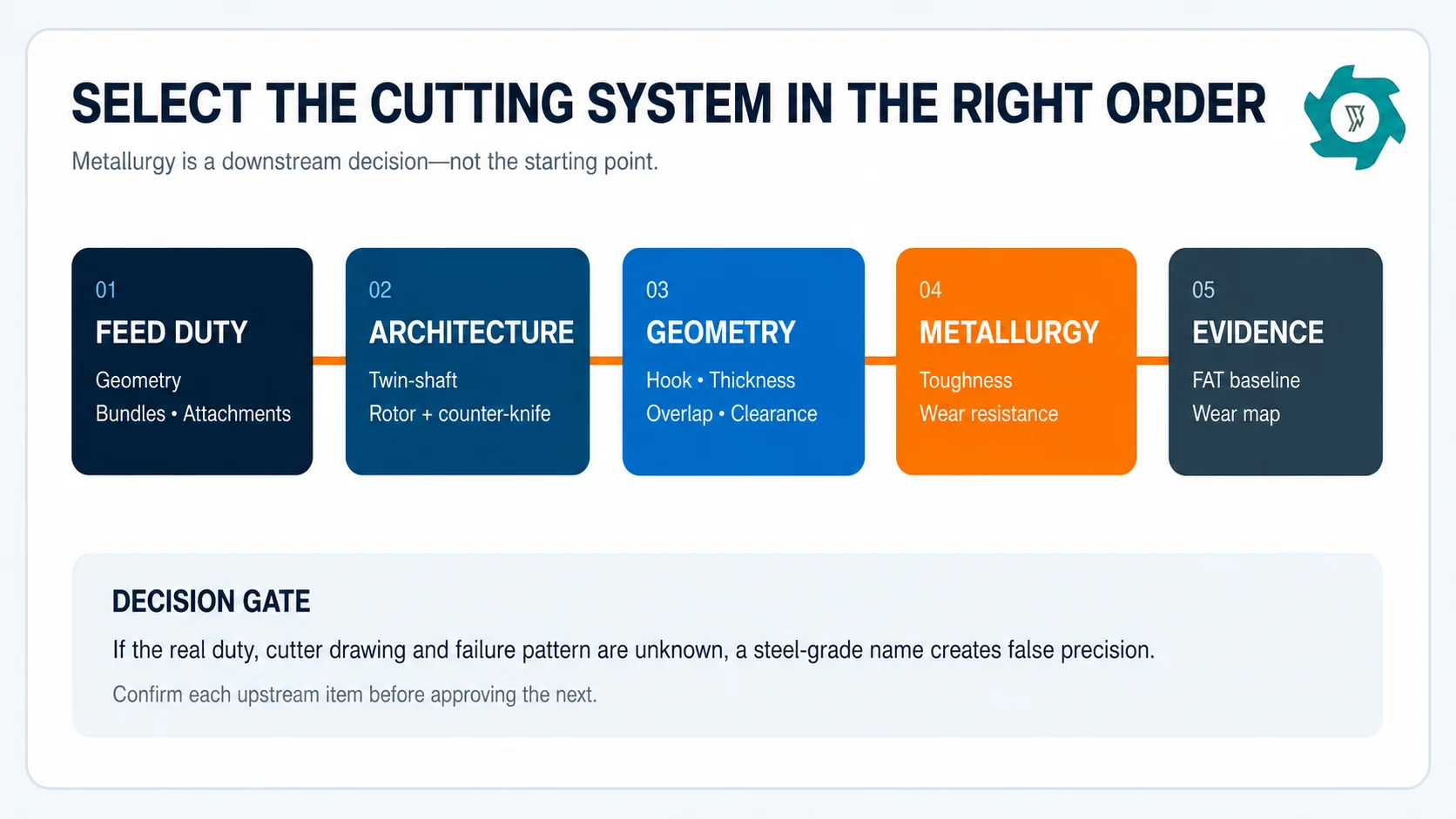
The useful selection sequence is feed envelope → machine architecture → cutter engagement → edge support and clearance → metallurgy and heat treatment → inspection and regrind plan. Reversing that order creates false precision. A familiar tool-steel name tells you little if the cutter is too thin for the shock load, the hook pulls several pieces at once, or shaft movement destroys the intended clearance.
The broader scrap aluminum recycling line can handle profiles, sheet, castings and mixed feed through different process routes.
Select metallurgy only after the feed duty, cutter architecture and geometry have been defined.
“Aluminum scrap” is not a cutting specification
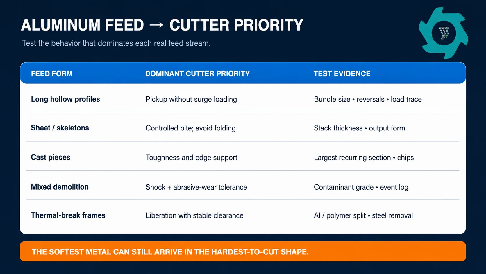
Aluminum is generally softer than ferrous scrap, but the chamber rarely sees a clean laboratory coupon. It sees a shape. Long hollow profiles bend and wrap. Stamping skeletons stack into a thicker bite. Cast pieces deliver concentrated shock. Thermal-break frames bring plastic strips and steel fasteners. Demolition aluminum may carry dirt, glass and attachments. These differences can change how many cutters engage, where force enters the edge and whether the dominant damage is rounding, adhesive build-up or impact chipping.
Write the feed envelope around recurring reality, not the average photograph:
largest normal length, width, wall thickness and solid section;
piece form: hollow, flat, nested, branched, compact or springy;
batching method and the maximum bundle that can reach the shafts;
attached steel, stainless, rubber, plastic, glass, soil and other minerals;
forbidden objects and the upstream method used to intercept them;
required output purpose: coarse handling, liberation or screen-controlled sizing;
accepted tons per hour and operating hours per shift.
Long-stock feeding deserves separate treatment because unstable presentation can make the cutter look like the problem. The aluminum profile feeding guide explains bridging and surge loading upstream. Likewise, clean sheet should first pass the shred, shear or bale decision; there is no blade benefit in processing material that did not need shredding.
Choose the cutter architecture before the metallurgy
Twin-shaft cutters: coarse pulling and primary reduction
Counter-rotating cutter discs are commonly evaluated when bulky or irregular scrap needs to be grabbed, torn and sheared into a coarse stream. Tooth count, tooth projection, disc thickness, overlap and spacer stack work together. A more aggressive hook may improve pickup, but it can also pull a larger bite and raise peak load. A thicker cutter adds section strength and changes the product; it does not automatically improve capacity.
A double shaft shredder is therefore a machine system, not two shafts with interchangeable discs. Replacement cutters must match the shaft interface, spacer stack, side clearance, axial retention and rotation map specified for that machine.
Single-shaft rotor knives: controlled sizing with a screen
Rotor knives working against fixed counter-knives can provide a more controlled discharge when a screen is part of the duty. Here, knife seating, counter-knife alignment, rotor-to-bed-knife clearance and screen load become central. Light sections that smear across a wide gap may create heat and irregular strips. An excessively tight or unstable gap can invite contact and edge damage. The correct cold setting must come from the OEM procedure and account for machine condition.
Hammer or impact tools are a different problem
Do not transfer knife-selection logic directly to impact shredders or hammer mills. Repeated impact, pin and rotor loading, hard inclusions and grate interaction create another stress regime. If the project uses an impact stage, its replaceable wear parts need a separate material and retention review.
Feed form changes the dominant cutter priority; one “aluminum blade” specification cannot cover every row.
Geometry controls how the load reaches the edge
Variable
What it changes
What to verify
Hook or tooth profile
Pickup, bite size and tendency to pull several pieces together
Stable feeding and peak load with the largest recurring bundle
Cutter thickness
Section strength, bite width and coarse output form
Required product condition and shaft/spacer design
Number and phasing of teeth
Simultaneous engagement and load distribution
Load trace, reversal frequency and discharge consistency
Overlap and clearance
Shearing versus folding, friction, heat and risk of contact
OEM setting, shaft runout, bearing condition and cold/hot behavior
Edge angle and support
Penetration versus resistance to chipping
Actual shock and contamination, not aluminum hardness alone
Mounting and spacer accuracy
Axial position, local rubbing and uneven load
Stack dimensions, clean seats, torque method and final rotation check
These variables interact. Narrowing clearance cannot compensate for a loose bearing. A stronger edge angle cannot stop a hard tool from entering the chamber. A more aggressive hook cannot fix a hopper that releases tangled profiles in surges.
Balance toughness, wear resistance and dimensional stability
The practical trade-off is not “hard blade versus soft blade.” It is edge retention versus the ability to survive shock without cracking, while maintaining dimensional accuracy through heat treatment and service. Tool-steel grade, heat-treatment route, hardness profile, cutter cross-section and surface finish belong in one supplier-controlled specification.
Clean, consistent, light-gauge feed may reward edge retention and accurate shearing. Cast pieces, fasteners and variable mixed feed raise the importance of toughness and edge support. Mineral contamination can accelerate abrasive wear even if the aluminum fraction is soft. Aluminum can also adhere at a cutting interface; peer-reviewed machining literature describes built-up edge and adhesion among the mechanisms encountered when cutting aluminum alloys.1
Procurement rule: require the OEM to state the cutter material specification, heat-treatment control, target property range, inspection method and regrind limit for the quoted geometry. Do not accept a grade name as the entire quality plan.
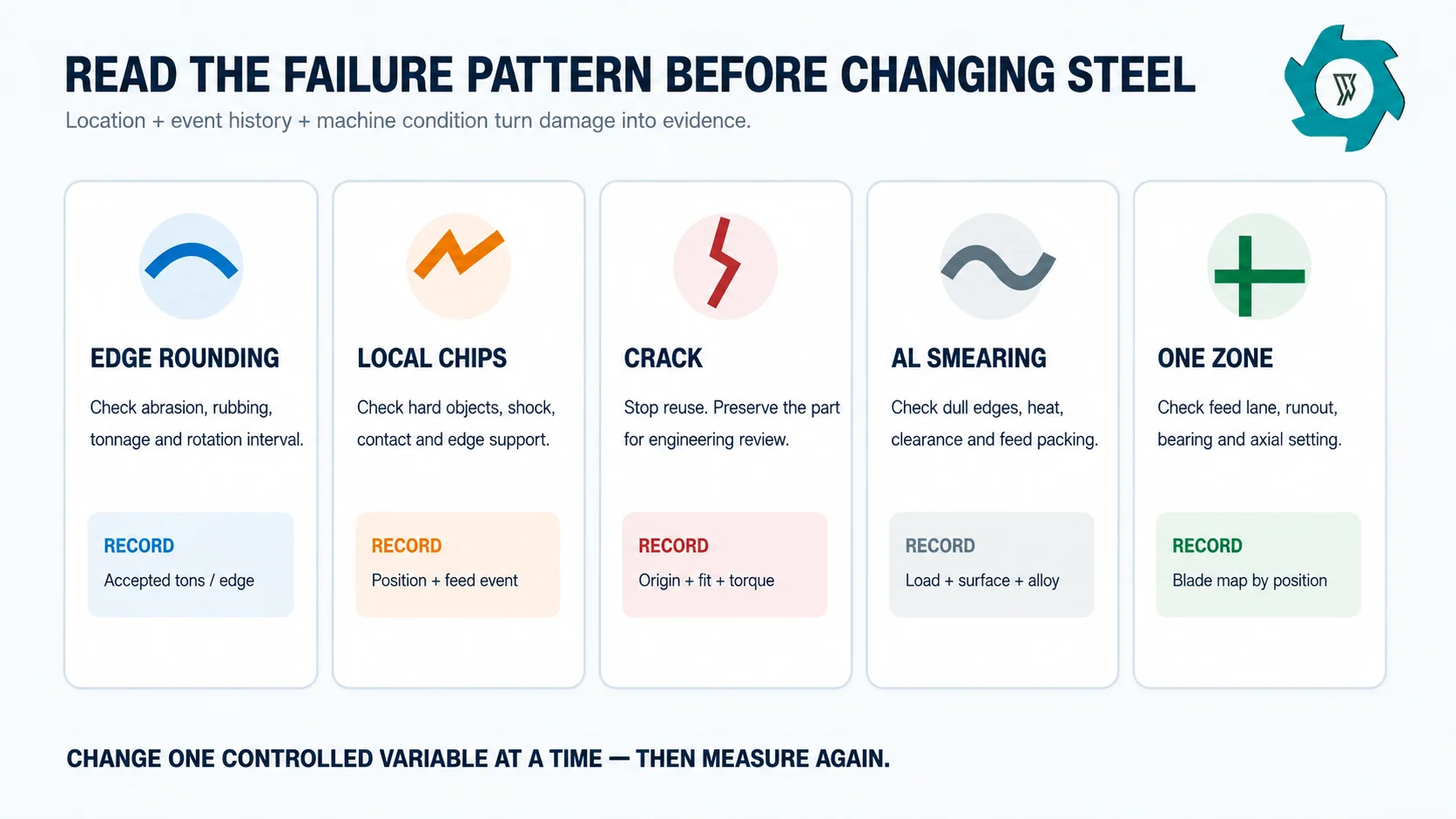
Diagnose the pattern before ordering “better” blades
Mixed aluminum streams should be graded and controlled before comparing wear. The mixed aluminum feed-control guide covers lot grading, contamination hold points and synchronized sampling. Without that discipline, a blade trial may only compare two different scrap batches.
Observed pattern
Likely contributors to investigate
Evidence to collect
Uniform edge rounding
Normal wear, abrasive dirt, excessive rubbing, long interval between rotations
Accepted tonnage, contamination grade, load trend, photos at fixed magnification
Localized chips
Hard inclusion, shock, acute edge, misalignment or contact
Chip position by shaft/disc, event log, foreign object, spacer and bearing checks
Crack from bore or key area
Fit, stress concentration, mounting damage, overload or material/heat-treatment issue
Do not reuse; preserve part, drawing, torque record and fracture location for engineering review
Aluminum smearing or build-up
Rubbing, heat, dull edge, large gap, feed packing or alloy/coating behavior
Surface photos, temperature/load trend, feed identity, clearance and cleaning practice
One shaft or zone wears faster
Uneven feed distribution, axial setting, runout, bearing condition or local contamination path
Blade map by position, hopper loading pattern, shaft/runout checks and output distribution
Visible damage is a diagnostic signal. Record its location and operating event before changing metallurgy.
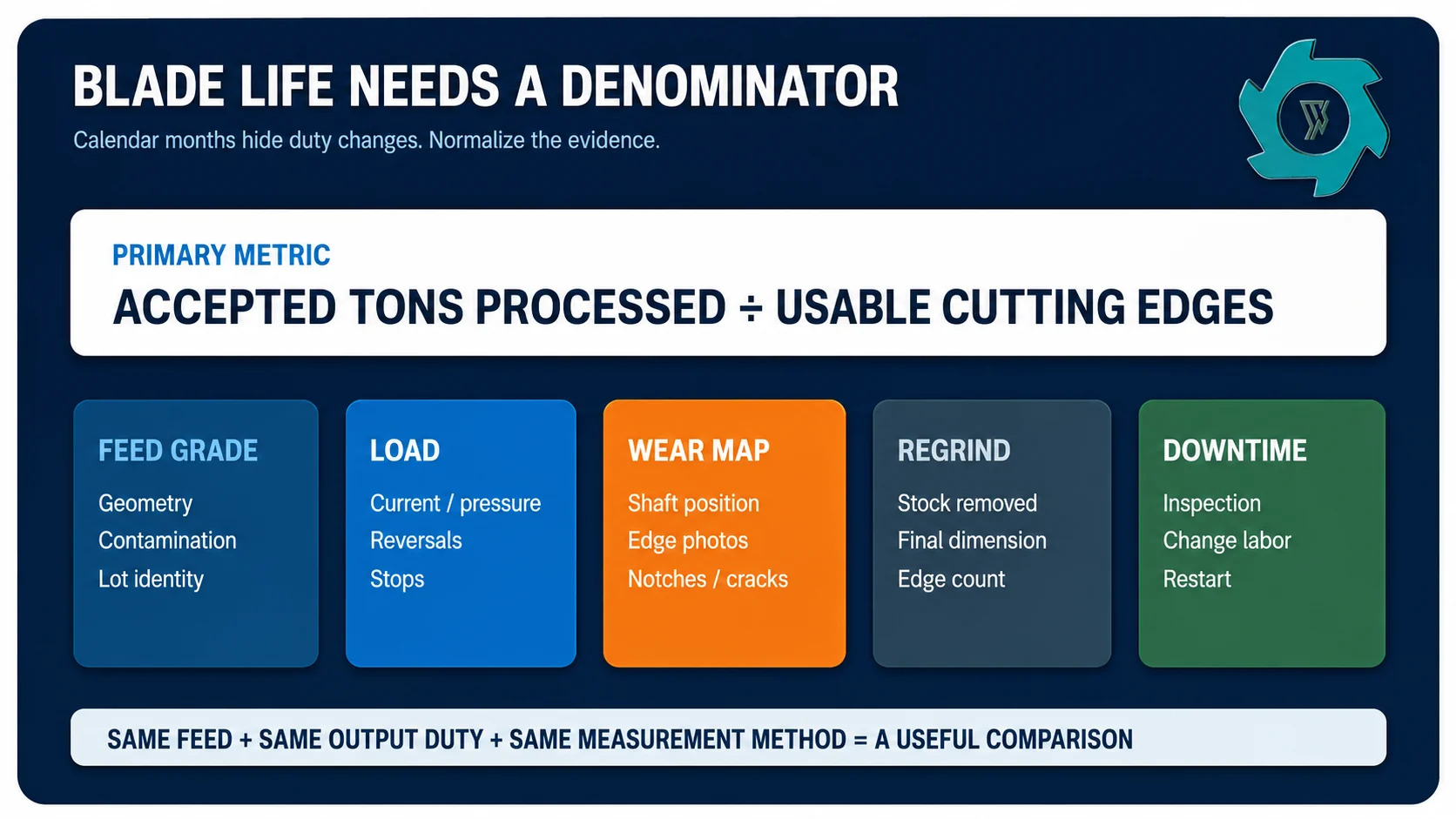
Measure blade life in accepted tons, not calendar days
One plant may run one shift on clean extrusions; another may run continuously on demolition scrap. Use accepted tons per usable edge under a named feed grade. Add operating hours, reversals per accepted ton, jam events, rejected feed, fines or output drift, and maintenance minutes.
Build a blade map. Give each shaft position and cutter face a permanent identifier. At each planned stop, photograph the same edges, record notch depth or another OEM-approved wear measurement, and note whether wear is uniform. This reveals whether the problem follows a cutter, a shaft position or a feed lane.
Rotation, regrinding and replacement
Rotate or index only when the cutter design allows it and the OEM procedure preserves the intended phasing. Regrinding must keep mating cutters compatible, restore the specified geometry, control heat input and respect the minimum dimension. Removing stock changes diameter, overlap, gap and spacer relationships. A visually sharp edge can still be outside the machine’s usable geometry.
Replace rather than regrind when cracks, severe chips, deformed mounting features or dimensions below the approved limit are present. Do not weld-repair, hardface or change heat treatment without written engineering approval for that exact cutter.
Turn the FAT into a future wear baseline
Divide the test feed into documented lots: normal production feed, the largest recurring pieces, the most difficult recurring geometry and an agreed level of normal contamination. Forbidden objects remain forbidden—they should test upstream rejection, not cutter survival.
Record:
gross feed, rejected feed and accepted output weights;
observation time and sustained accepted throughput;
motor current or hydraulic pressure trend, not only a single peak;
automatic reversals, operator interventions and complete stops;
output-size or liberation checks tied to the downstream purpose;
fines and all meaningful output streams where relevant;
cutter photographs and blade-map condition before and after;
the exact drawing revision, cutter set, spacer stack and setting procedure.
If field load, reversals or contamination differ sharply from FAT conditions, the team can investigate the changed duty before blaming the blade.
A blade-life claim becomes comparable only when feed severity, accepted tonnage and intervention data travel with it.
RFQ checklist for cutters and spares
Machine and shaft drawing revision; cutter and spacer part numbers.
Feed envelope with representative photos, lot mix and attachments.
Target process result and permitted oversize or recirculation.
Cutter geometry, material specification and heat-treatment quality controls.
Dimensional inspection report and traceability for each production batch.
Approved cold-clearance or stack-setting procedure and tolerances.
Rotation, regrind and minimum-useful-dimension instructions.
Expected inspection interval stated as a starting point, not a guarantee.
Critical-spares quantity based on lead time and planned maintenance window.
Method for reporting chips, cracks or unusual wear to the OEM.
Safety boundary: blade work is hazardous-energy work
Inspection, blockage clearing and blade replacement can expose workers to stored mechanical, electrical and hydraulic energy. OSHA’s lockout/tagout standard covers servicing and maintenance where unexpected energization, startup or release of stored energy could cause injury.2 OSHA also requires guarding against hazards including ingoing nip points, rotating parts and flying material.3 HSE guidance similarly calls for safe maintenance, isolation and prevention of inadvertent reconnection on high-risk equipment.4
The site-specific energy-control procedure, competent personnel and machine manual must govern the job. A visual check from outside a protected area is not permission to reach into the chamber. Noise should also be assessed as a workplace exposure; NIOSH has published recycling-specific hearing-loss guidance.5
Need a Cutter Review for Real Aluminum Feed?
Send the machine configuration, cutter drawing, representative feed photos, largest recurring pieces, contamination notes, target output and current wear photographs. We can review the cutting duty and the evidence needed for a controlled trial.
Frequently Asked Questions
What is the best blade material for shredding aluminum?
There is no universal best grade. The correct choice depends on cutter section, heat treatment, feed geometry, attached steel, mineral contamination, shock loading and the way the current blade fails. Ask the shredder manufacturer to match metallurgy and hardness to representative feed and the complete cutter design.
Why do aluminum shredder cutters chip?
Chipping often points to shock, hard foreign material, insufficient edge support, misalignment or a cutter condition that is too brittle for the duty. Map where chips occur, identify the feed event and inspect spacers, shafts and bearings before changing steel grade.
Does a sharper cutter always reduce power use?
A sound cutting edge can reduce tearing and repeated reversals, but an edge made too acute for the load may chip. Power also depends on feed rate, cutter engagement, clearance, contamination and drive control, so sharpness should be evaluated with throughput and load data.
How should blade life be compared?
Use accepted tons processed per usable edge under a defined feed and output duty. Record reversals, foreign-object events, regrind stock removal and downtime as well. Calendar days alone hide changes in operating hours and feed severity.
What should be included in an aluminum shredder blade FAT?
Run representative normal, difficult and recurring contaminated feed. Record accepted throughput, motor or hydraulic load, reversals, jams, output condition, fines, cutter condition before and after the run, and the exact cutter drawing and metallurgy supplied.
David focuses on industrial shredding and recycling equipment,including material evaluation,shredder selection,process configuration,and recycling line planning.
Speak To Our Shredder Machine Expert
Get in touch with our nice team today to get a price estimate for a shredder machine.

 English



 Fast Delivery
 Reliable
 Certified
 Experienced