Industrial Shredder & Recycling Systems Manufacturer - YUXI

 English

 English
 Fast Delivery
 Reliable
 Certified
 ExperiencedEnglishEnglishFast DeliveryReliableCertifiedExperienced
Follow the material from the feeding hopper through grabbing, primary cutting, secondary cutting, recirculation, screen control and final discharge.
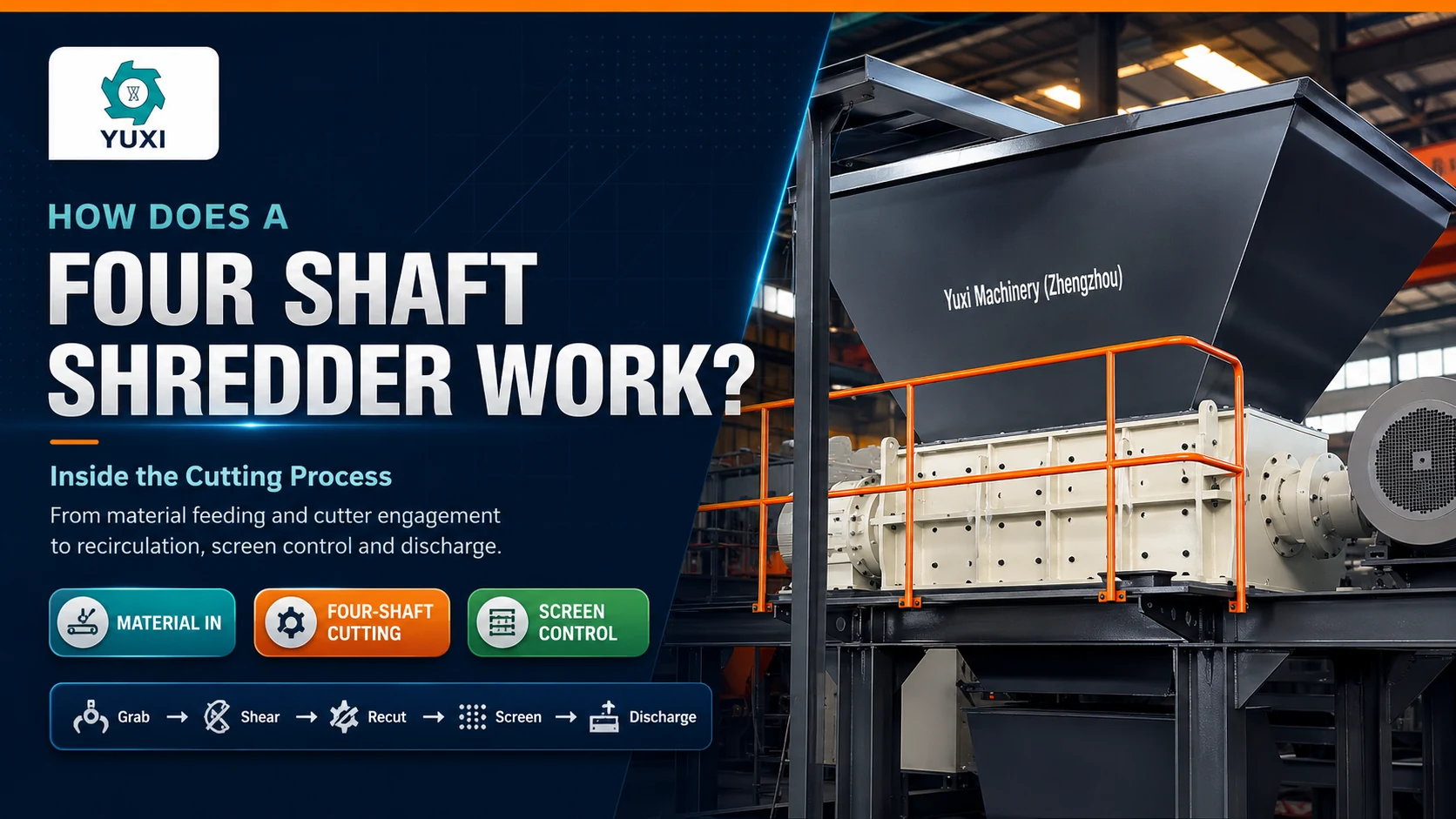
A four shaft shredder uses four low-speed cutter shafts to grab, shear and repeatedly reduce bulky or mixed material. Depending on the design, the machine may use two upper and two lower cutting stages, or two primary cutting shafts together with two clearing or secondary shafts. Material that is still larger than the selected screen opening remains in the chamber for more cutting. Once it can pass through the screen, it moves to the discharge conveyor or downstream separation equipment.
When material disappears below a four shaft shredder hopper, it does not simply pass once between four rotating knives and fall onto a conveyor. A plastic drum may be punctured, released, turned and cut several times. A piece of thin sheet metal may fold before it tears. Textile-rich RDF may stretch across more than one cutter before it finally separates. Oversized fragments remain in the chamber because the screen will not let them leave.
That repeated interaction is the real value of the machine. Four shafts provide more opportunities to catch awkward feed, change its direction and expose a new edge to the cutters. The screen then gives the process a clear stopping condition: material can leave only after it reaches a usable size and shape for the next stage.
Not every manufacturer arranges the four shafts in exactly the same way. Some machines use two upper shafts for grabbing and initial reduction with two lower shafts for additional cutting. Other designs use two main cutting shafts and two clearing shafts. The terminology changes, but the engineering objective is similar: maintain contact with the feed, prevent premature discharge and create a controlled product for separation, granulation, washing, baling or fuel preparation.
A four shaft shredder is a low-speed, high-torque industrial size-reduction machine equipped with four parallel shafts inside one cutting chamber. Intermeshing cutters create several grabbing and cutting zones. A replaceable screen is normally installed below the shafts so that fragments that are still too large remain in the machine for another cutting cycle.
The machine is commonly used where a basic rough shred is not enough. Mixed electronic waste may need to be opened before magnetic and eddy-current separation. Plastic drums may need a consistent feed size before washing or granulation. RDF preparation may require long pieces to be shortened before screening, drying or thermal use. In each case, output control matters as much as the first bite.
The four-shaft layout should not be treated as one universal mechanical pattern. For example, WEIMA describes a standard arrangement with two cutting shafts and two clearing shafts, while other manufacturers use upper and lower cutting stages. The exact role of each shaft should therefore be confirmed from the machine drawing rather than assumed from the name “four shaft.” This four-shaft design explanation is a useful example of the cutting-and-clearing layout.
Material reaches the machine by belt conveyor, chain conveyor, grab crane, loader or controlled manual feeding. Gravity moves it toward the cutter shafts, but the hopper does more than hold material. Its throat width and wall angle influence orientation, bridging and the size of each batch that reaches the cutting zone.
Rigid boxes and drums usually slide down easily until their flat surfaces rest across the shafts. Film, sacks, fishing net and textile bundles can bridge above the opening. Hollow plastic items may bounce or rotate when the first cutter touches them. A stable feed system meters the material so the shafts remain loaded without being buried under a sudden mass.
Each cutter disc has one or more hooks or teeth. As adjacent shafts counter-rotate, the hooks enter the material from different directions and create gripping points. Once a hook penetrates a drum wall, appliance shell or compressed bundle, the shaft rotation draws the material toward the center of the cutting zone.
This active grabbing is one reason a four shaft machine can process awkward bulky feed without relying on one continuous hydraulic pusher. The cutters themselves pull material inward. Some projects still use a pressing device or ram hopper when the feed is extremely light, springy or prone to bridging. In that case, the pusher supports stable engagement; it should not be used to force unsuitable heavy objects into the cutters.
The first useful reduction occurs when material is trapped between rotating cutter edges, adjacent shafts and the chamber structure. The cutters apply localized shear and tearing forces. A plastic drum is punctured and split. A computer housing cracks open. A folded metal sheet is pinched, bent and cut. RDF is stretched until fibers and film separate.
The word “shredding” can hide several different actions. The machine does not simply grind everything into chips. Tough flexible material is torn. Thin rigid material is sheared. Brittle plastic fractures around the contact point. Hollow objects collapse before the wall is cut. Understanding that behavior is important because each action creates a different load pattern and output shape.
After the first opening, the material is no longer one large object. It becomes a moving mixture of strips, plates, chunks and partially separated components. The second pair of shafts keeps those fragments moving through active cutting zones instead of allowing them to rotate freely above the screen.
In an upper-and-lower arrangement, the upper shafts perform the first grabbing and opening, while the lower shafts continue reducing the material near the screen. In a cutting-and-clearing arrangement, the clearing shafts remove fragments from the spaces between cutter discs and push them back toward an effective cutting path. Both approaches aim to reduce dead zones and keep irregular material from riding around with the cutters.
A fragment that reaches the lower part of the chamber is not automatically finished. If it cannot pass through the screen, continued shaft movement lifts, turns or pushes it back into contact with the cutters. The fragment approaches from a new direction and receives another bite.
This recirculation may happen several times. The process is especially useful for flat panels, folded sheet, appliance housings and bulky mixed waste because the first cut often creates long or irregular pieces. Repositioning exposes a different edge, shortens the fragment and reduces the probability that an oversize piece will enter the next conveyor or separator.
The screen is not a cutting blade, but it is an active part of the working principle. It creates the boundary between unfinished material and qualified discharge. Large fragments remain supported close to the cutters, while smaller pieces fall through the openings.
Franklin Miller describes quad-shaft machines with removable sizing screens that retain material until it reaches a predetermined size. That is the central difference between controlled four-shaft reduction and a simple coarse shred. Its quad-shaft overview also shows how the screen works together with precision cutters rather than acting as a separate downstream classifier.
A 40 mm screen does not promise that every piece will be a precise 40 × 40 mm square. Flexible film can fold through an opening. Thin metal can curl. Textile can pass as an irregular bundle. The screen limits the available exit path, while cutter thickness, hook design, material orientation and repeated cutting determine the final shape.
Once fragments pass through the screen, they leave by gravity chute, belt conveyor, screw conveyor or another matched discharge system. The following equipment may include a magnetic separator, eddy-current separator, trommel, air separator, granulator, washing line or baler.
The discharge system must handle short surges. Material can remain in the chamber for several cycles and then leave quickly once it reaches the screen requirement. A narrow or slow conveyor may become the actual production bottleneck even when the shredder is working normally.
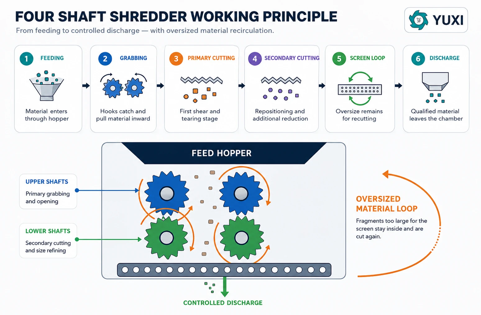
Adjacent shafts normally rotate toward one another at the main intake points. The facing cutter hooks move down into the chamber and pull the material between them. If both surfaces moved in the same direction, a flat item could travel across the top rather than entering the cut.
Some machines use different cutter profiles or speeds on different shafts. One pair may be more aggressive for grabbing, while another pair maintains clearance and recutting near the screen. A small speed difference can also change the contact point and discourage flexible material from wrapping around the shaft stack.
Cutter discs are separated by spacers, and the discs on the neighboring shaft enter those spaces. The overlap forms a series of narrow cutting gaps along the shaft length. Material is trapped between a cutter edge and the opposing disc or spacer, producing a scissor-like action.
The benefit is not simply twice the cutting power of a double shaft machine. The additional shafts create more contact points and more chances to turn a fragment. A long strip that escapes one cutting gap can be caught lower in the chamber and presented from another angle.
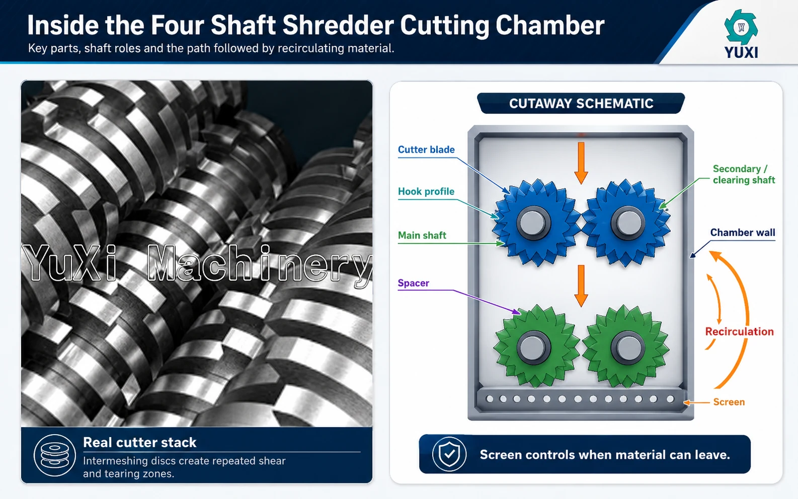
Shearing occurs when material is caught between adjacent cutter edges and the forces move in opposite directions. It is important for thin sheet metal, plastic plate, containers and electronic housings. Sharp edges and controlled clearance produce a cleaner cut; worn edges increase bending and tearing before separation.
Tearing occurs when hooks hold different parts of the same object and pull them apart. It is common with RDF, film, woven sacks, textile, rubber and composite waste. The hook must grab deeply enough to prevent the material from sliding, but an overly aggressive bite can create high current peaks.
Brittle plastics, wood-based products and hard housings can crack around a localized contact point. The cutters start the crack, and shaft movement extends it through the material. Fracture can produce a wide distribution of shapes even when the screen controls the largest discharge path.
Material is compressed between cutter faces, shafts and the chamber before it separates. Compression helps collapse hollow items and creates stress that supports the cut. A four shaft shredder is not primarily a compression crusher, however. Excessive crushing without cutting wastes energy and may indicate blunt cutters or an unsuitable profile.
The electric motors turn much faster than the cutter shafts. Heavy-duty gear reducers lower the rotational speed and increase usable shaft torque. The resulting slow, controlled bite is better suited to bulky and mixed material than a high-speed impact process.
Low speed provides several practical benefits:
Motor kilowatts alone do not describe this performance. Shaft torque also depends on reduction ratio, shaft speed, cutter diameter, gearbox efficiency, service factor and how many shafts are loaded at the same moment. Two machines with the same installed power can respond very differently to the same drum or appliance shell.
Smaller openings retain more fragments. Residence time increases, more cutter contacts are required and average motor load usually rises. The result is finer or more controlled discharge, but throughput falls and cutter and screen wear increase.
Larger openings allow fragments to leave after fewer cutting cycles. Throughput normally improves and heat generation is lower, but the output contains larger and sometimes longer pieces. That may be acceptable for pre-sorting or baling but unsuitable before a small granulator.
Wet labels, textile, film, mud and oil can cover the screen openings. The machine then behaves as if a much smaller screen were installed: material remains inside, current rises and discharge becomes irregular. Operators may incorrectly blame the motor or cutter when the real problem is reduced open area.
The screen receives repeated abrasion and occasional impact. It needs enough support to resist deformation, yet it must be accessible for inspection and replacement. A damaged screen can release oversize material and remove the main process advantage of the four-shaft design.
| Material | What Happens Inside the Chamber | Main Working Challenge |
|---|---|---|
| Plastic drums | Hooks puncture the wall, collapse the hollow body and tear it into panels and strips. | Drums may bounce, rotate or bridge before the first hook gains a firm grip. |
| E-waste | Housings crack open and internal metal, wire, plastic and boards are progressively liberated. | Hidden metal parts, glass and batteries create impact and safety risks. |
| RDF/SRF | Flexible pieces are stretched between cutters and shortened through repeated tearing and shearing. | Film and textile can wrap; moisture changes density and screen behavior. |
| Bulky waste | Large items are gripped, folded and opened before smaller sections reach the screen. | Mattresses, furniture and mixed shapes create bridging and uneven loading. |
| Light metal scrap | Thin sheet bends, folds, shears and tears as the cutter edges gain purchase. | Hidden solid pieces cause torque spikes and cutter-edge damage. |
| Industrial packaging | Plastic, light metal, labels and residue are reduced together before separation or washing. | Liquids, chemical residue and contamination require a separate safety review. |
The examples show why one screen and cutter configuration cannot produce identical behavior across every material. A brittle housing can break quickly and pass through the screen, while a flexible strip of the same width may continue circulating because it bends instead of presenting a clean cutting edge.
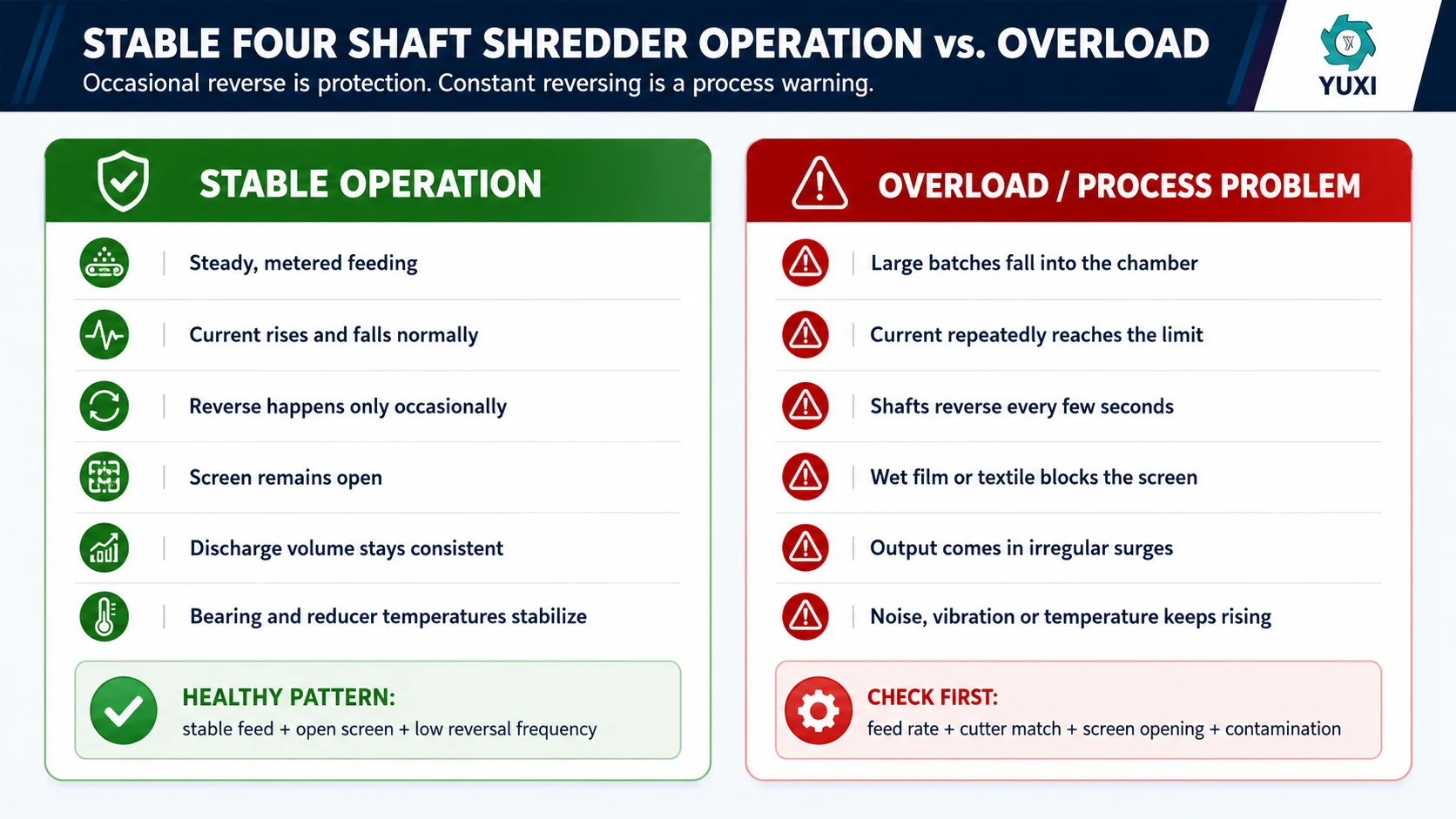
An overload begins when cutting resistance rises above the normal operating range. The cause may be a dense foreign object, a large batch, an unsuitable cutter bite, a blocked screen or material wrapped around a shaft.
Automatic reverse is a protection function, not a substitute for correct process design. Occasional reversing shows that the machine has responded to an irregular object. Reversing every few seconds usually means the feed rate, cutter profile, screen opening or duty rating is wrong for the real material.
A good control system also interlocks the feeding and discharge conveyors. When the shredder current rises, the feed conveyor pauses before more material enters. When the discharge conveyor stops, the shredder should stop before processed material fills the space below the screen.
The screen is the most visible size-control component, but it is not the only one. Final discharge is produced by the interaction of:
With the same 40 mm screen, brittle plastic may leave as compact irregular chips. Thin metal may leave as curled flakes. Film may appear as folded strips. Textile may leave as a loose fibrous bundle. The screen prevents obviously large pieces from leaving, but it does not turn every feed material into the same particle geometry.
| Feature | Double Shaft | Four Shaft |
|---|---|---|
| Main action | Coarse grabbing, tearing and volume reduction | Grabbing, repeated cutting and screen-controlled discharge |
| Cutting path | Usually one primary cutting zone | Several interacting cutting or clearing zones |
| Screen | Often not required for primary shredding | Normally central to output control |
| Oversize fragments | May leave with the coarse discharge | Remain for additional cutting |
| Typical role | Pre-shredding and volume reduction | Controlled size reduction before downstream processing |
A four shaft machine is not automatically the stronger choice. For rough opening, a simpler double shaft shredder may provide higher efficiency and easier maintenance. A detailed four shaft shredder vs double shaft shredder comparison should be used when the decision depends on controlled output rather than shaft count.
A single shaft shredder normally uses one rotor, fixed counter knives, a hydraulic pusher and a screen. The pusher forces relatively consistent material against the rotor. A four shaft machine uses several active shafts to grab and reposition bulky or mixed feed. Both can use screens, but the way material reaches and returns to the cutting zone is different.
A machine does not need to run at perfectly constant current. Shredding irregular material naturally produces load changes. Stable operation means the changes remain inside a repeatable range and the process recovers without continuous operator intervention.
These signs should be investigated as a process problem, not hidden by increasing the overload setting. Raising the current limit may postpone a trip while transferring the load to the cutters, shafts, bearings or reducer.
The basic sequence remains feeding, grabbing, cutting, recirculation and discharge. The way it feels in production changes considerably with the selected configuration.
Thin cutters create more cutting lines across the shaft width and may produce narrower strips. Thick cutters provide greater section strength and are often preferred for impact duty. The screen still controls the exit, so thin cutters should not be selected only because the target output is small.
Deep hooks grab hollow and slippery items aggressively. More hooks create more frequent contact but reduce the amount of material supporting each tooth. Flexible feed needs a profile that cuts cleanly rather than wrapping.
The screen controls residence time. Smaller openings increase recirculation and load; larger openings release material sooner. Output size should be chosen from the next process backward.
Lower speed generally increases available torque and gives the control system more time to respond. Higher speed may improve volume throughput for easy material but can increase wrapping, heat and impact when the feed is irregular.
A grab crane creates larger batches than a metered conveyor. A loader may place material on one side of the chamber. The same shredder can show very different current and capacity results simply because the feeding method changed.
Sand and glass accelerate abrasive wear. Wire and textile increase wrapping risk. Wet labels block screen area. Hidden solid metal causes high torque peaks. These factors do not change the theoretical sequence, but they decide whether the sequence remains stable.
For complete line projects, the shredder should be evaluated as one stage in a waste metal shredding and recycling system, not as an isolated machine. The next separator or granulator defines how much size control the shredder actually needs.
A technically honest working-principle guide should also explain the limits. A four shaft shredder may be unnecessary or unsuitable when:
In those cases, adding more shafts does not solve the fundamental process mismatch. The correct answer may be a simpler pre-shredder, a dedicated heavy-metal machine, a tire shredder or a two-stage system.
Material enters the hopper → cutter hooks grab and pull it inward → primary shafts open and shear the feed → secondary or clearing shafts redirect and cut it again → oversized pieces remain above the screen → repeated cutting continues → qualified material passes through the screen → the conveyor moves it to the downstream process.
Four shafts do not create value simply because there are more rotating parts. The value comes from controlling contact with the material. The machine catches difficult feed, changes the direction of partially cut fragments and continues working until the screen confirms that the material is ready to leave.
The operating result therefore depends on the complete system: hopper, feeding method, cutter profile, shaft layout, gearbox, PLC logic, screen and discharge conveyor. When those elements match the real material, a four shaft shredder can provide a stable, controlled feed for separation and further recycling.
Purchase cost and operating cost also change with the shaft, screen and maintenance arrangement. The separate four shaft shredder price guide explains why machines with similar motor power can have very different quotations and lifetime costs.
Send representative material photos or video, feed size, contamination, target output, capacity and downstream equipment. YUXI can review the cutter, screen, shaft and control requirements before quotation.
They create several grabbing, cutting and material-clearing zones. Depending on the design, two shafts may perform the main cutting while the other two clear and redirect fragments, or upper and lower pairs may provide two cutting stages.
No. Shaft position, cutter profile, relative speed and the role of each shaft vary by manufacturer. Confirm the arrangement from the mechanical drawing rather than assuming all four shafts perform identical work.
A screen below the cutters retains fragments that are too large. Shaft movement redirects them into another cutting cycle. Material leaves only after it can pass through the selected screen opening.
Usually not. Large or long fragments may be cut several times. Recirculation inside the chamber is one of the main reasons a four shaft shredder can produce more controlled discharge than a coarse two-shaft machine.
Gear reducers convert motor speed into high shaft torque. Low-speed cutting improves gripping, limits high-speed impact and gives the overload system time to stop or reverse when resistance becomes excessive.
The control system detects rising current or pressure, stops the shafts and reverses them to release the tight cutting point. If repeated attempts fail, the machine stops and alarms for inspection.
No. The screen controls the exit path, but cutter thickness, material flexibility, orientation and wear affect the final piece shape. Film, textile and thin metal can leave in irregular or folded forms.
No. Four shafts are useful when repeated cutting and screen-controlled discharge are required. A double shaft machine is often more economical for rough opening and volume reduction.
It can process suitable light metal and mixed electronic waste when cutters, shaft strength, screen and protection match the material. Batteries, solid metal pieces and hazardous components should be removed or evaluated before shredding.

Get in touch with our nice team today to get a price estimate for a shredder machine.
Contact Us